River Hydraulics in Steep Canyon Environments


By John Hunt, PE; Will deRosset, PE, CFM; and Anthony Alvarado, PE, CFM
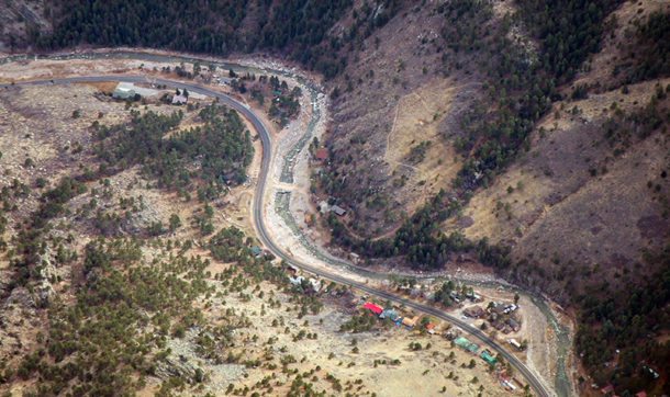
The September 2013 flood in Colorado devastated the northern Front Range, causing widespread damage to critical infrastructure and transportation networks. Hundreds of miles of roads were washed out, cutting off access to many small mountain towns. The flooding was especially devastating in mountain corridors north of Denver, including the Big Thompson River canyon, where it destroyed over 10 miles of the US 34 roadway embankment, washed out homes, and took two lives.
US 34 stretches from the City of Loveland west to the tourist town of Estes Park at the base of Rocky Mountain National Park. It is the main route for tourists to reach Estes Park and the park; the flood not only cut access, but also negatively impacted the region’s tourism industry. Reopening the highway was of utmost importance to the Colorado Department of Transportation (CDOT), and an emergency repair was completed in a matter of weeks. The emergency repair work was, however, only temporary.
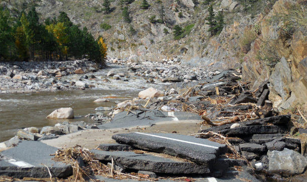
Permanent repairs for US 34 involved not only transportation and other related engineering services, but also complex hydraulic engineering. The US 34 corridor cuts through a steep canyon environment, posing challenges unique to projects in this type of topography. The highway follows the path of the Big Thompson River, framed by steep canyon walls. Driving forces leading to the flood damage were high velocities and depths of flood flows caused by the steep, confined, and constricted river in the canyon reach. The velocities and hydraulic shear stresses were extremely high, and the destructive forces were severe. Essentially, wherever you have a highway running alongside a river in a steep canyon environment, the highway can be exposed to severe damage in flood events.
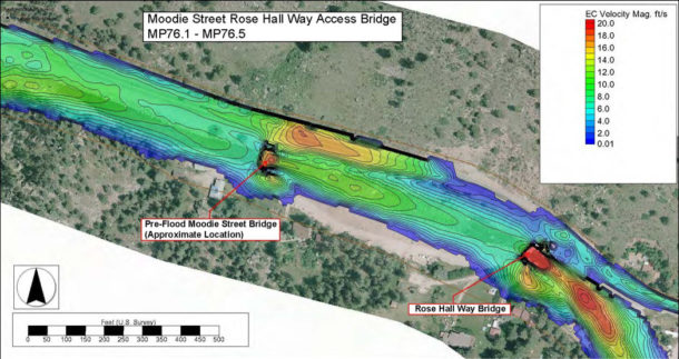
Ayres Associates used two-dimensional hydraulic modeling to successfully recreate the conditions of the 2013 flood. Sections of the highway where the model predicted a high erosion potential proved to be consistent with the reality of what happened in the flood. With this validation of the modeling technique, Ayres completed model simulations of future design flood conditions for the proposed highway configuration. The results of the modeling were used to:
- Determine the correct size of rock riprap for protecting the highway embankment.
- Figure out how deeply the embankment protection needed to be embedded into the ground.
- Assess the impacts of access bridge design.
- Determine any potential negative impact of the design on the opposite bank.
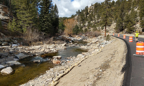
Important to this process was designing armoring and other treatments to protect the highway embankment from suffering the same level of massive destruction in a future 100-year flood as had occurred in the 2013 flood. This armoring, or embankment protection, came in the form of conventional loose rock riprap and, where the required loose riprap size would be excessively large, an innovative technique called matrix riprap. Matrix riprap requires using much smaller-sized rock than traditional riprap and cementing the pieces together with a mortar adhesive mixture, resulting in a highly interlocked and erosion-resistant armor layer that is approximately one-half to two-thirds the thickness of ordinary riprap of equivalent performance. Matrix riprap provides significantly increased hydraulic stability compared to loose riprap while retaining riprap’s articulation and superior conformation to irregular slopes.
Ultimately the US 34 hydraulic analysis demonstrates how river canyon environments pose stability threats to parallel highways, as the steep longitudinal slopes lead to extreme flood velocities and shear stresses. In turn, this warrants the use of innovative embankment protection methods, such as matrix riprap, as well as using 2D modeling as the tool of choice for the hydraulic analysis. Specifically, engineers used the SRH-2D program, within the SMS modeling system, in combination with ArcGIS tools to create an automated procedure to rapidly perform scour calculations and riprap stone sizing for the entire project length and for shorter reaches where needed.
Using 2D hydraulic modeling instead of conventional one-dimensional modeling was necessary for this type of project because of its greater level of accuracy and the amount of information it provides. Having an accurate understanding of the velocity, depth, and shear stress in specific locations on an embankment or within a river channel is critical, and 1D modeling doesn’t provide that. Moreover, the 2D hydraulic modeling approach to the design of highway protection in this type of canyon environment sets a template for future highway design projects within canyon environments in similar settings.


Post a comment: