How Computational Fluid Dynamics Modeling Solved Aging Dam Dilemma
 By Matthew Hickox, PE
When complex issues at dams arise due to rapid change or unforeseen deterioration, industry standard design equations and methodologies developed in the 20th century cannot always provide the correct solution. Fortunately, engineers are increasingly able to turn to computational fluid dynamics (CFD) models to confirm the hydraulics situation so that appropriate measures or repairs can be applied. For a broad overview of CFD capabilities, check out our post, What is Computational Fluid Dynamics?.

About the Expert:
Matthew Hickox, PE, brings civil engineering expertise in stormwater and river design, planning, and construction phase services. His experience is founded on a solid understanding of hydrologic modeling, 1- and 2-dimensional hydraulic modeling, in-stream hydraulic structures, scour protection measures, culvert and bridge hydraulics, and the regulatory environment for stormwater projects.
How Does CFD Work in Practice?
In one recent case, stream hydrology and geomorphology had changed around a low head diversion dam. Located in a sand bed stream system downstream of what has been a rapidly developing urban area for the last several decades, the dam’s issues were compounded by several things happening in the stream system around it. Growing urbanization had increased not only the frequency of discharges, but also increased the base flow. A hydraulically steep system meant that a change from ephemeral tributaries to annual base flow also increased the sediment load as the upstream reaches eroded.
This combination meant that the stream channel downstream of the diversion dam had dropped 3-4 feet over the last 15 years, velocities had increased on the stilling basin apron with the reduced tailwater, and the sediment load causing abrasion on the face of the structure had increased. None of these issues were a fault of the diversion dam’s original design, but the changing stream hydrology and geomorphology caused conditions that were not anticipated by the original designers.
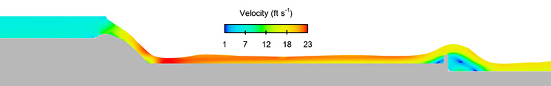
A unit width CFD model of the existing structure confirmed field observations that the existing site conditions did not cause a hydraulic jump to form on the stilling basin apron – this jump washed off the structure, causing further damage potential directly downstream of the structure (see Figure 1).
A similar unit width CFD model developed with the downstream stream bed elevation at the design elevation (pre-degradation) showed that the original design creates the hydraulic jump on the stilling basin apron and near the toe of the spillway face. While this unit width CFD model provides valuable verification of the hydraulics impacting the structure, this is not enough as the damage to the structure is very pronounced in the middle of the structure and nearly untouched in other areas. (Figure 2)

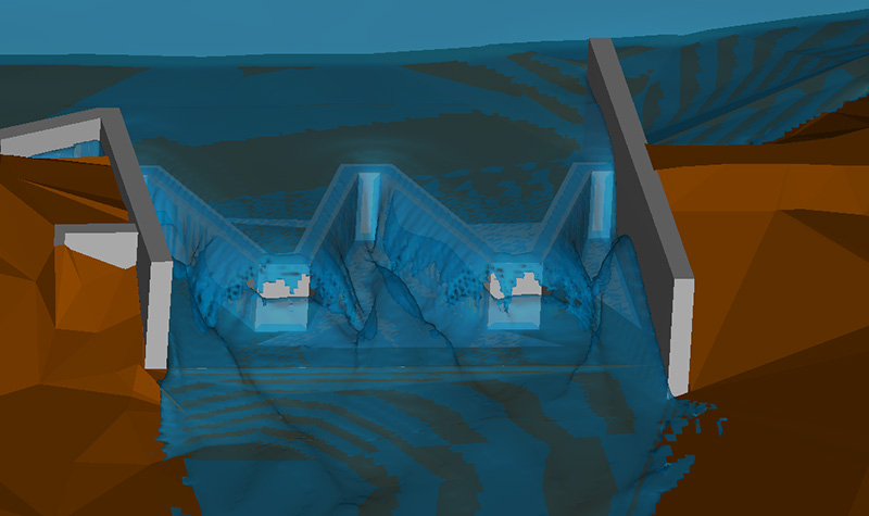
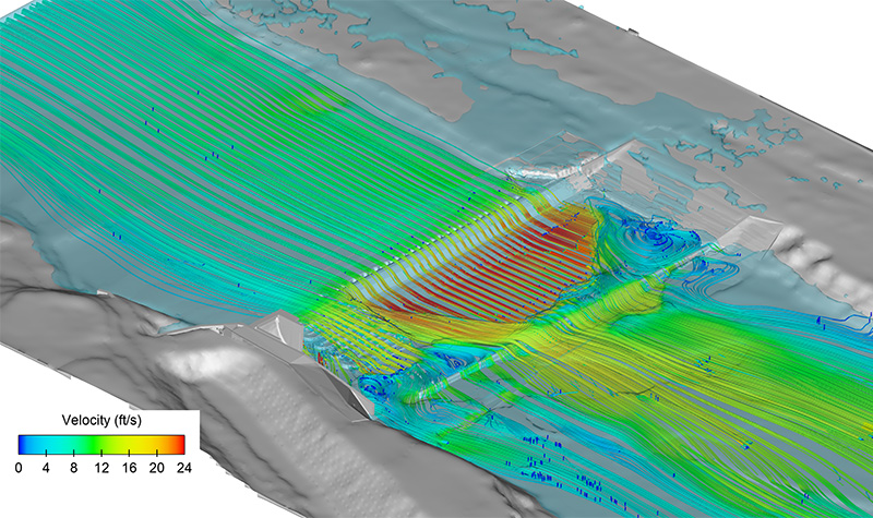
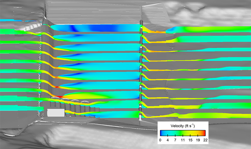
The full existing conditions CFD model confirmed the extents of the stilling basin apron abrasion and the resulting damage. (Figures 3 & 4)
During the preliminary design of the repair for this structure, a brief analysis showed that raising the tailwater on the structure would help create a hydraulic jump on the structure near the toe of the spillway, which would reduce the extreme velocities across the stilling basin apron and thereby significantly reduce the abrasion on the structure (see Figure 5). This preliminary proposed conditions CFD model only raised the end sill elevation; the condition and geomorphology of the stream system downstream of the structure will have to be evaluated for any final design condition to ensure the stability of the structure for the remainder of its design life.
CFD models give us another tool to confirm the hydraulics when design situations do not fall neatly within the limitation of established design equations and procedures. A holistic view, both detailed at the structure and an overview of the watershed, is needed to assess conditions now and in the future at a project site. The design and operation of the structure in this example remain very close to the original design – it is the stream system that has changed around the structure. CFD provides another tool in the toolbox to analyze complex hydraulics when changing site conditions result in unexpected hydraulics and structure damage.
For more information regarding CFD or the hydraulic engineering services we offer here at Ayres, please contact our River Engineering + Water Resources experts.
Comments
While modeling on GeoHECHMS I was thinking about this computational fluid dynamics, and here it is. I must say you’ve explained it very well.


Post a comment: