BIM Delivers Dividends on Unusual Structure Upgrades
 By Pete Haug, PE
Building information modeling (BIM) can play a big role in keeping the wheels from coming off an intricate project. We’ll look at a case study of a turbine and powerhouse upgrade project where the goal was to minimize changes to the exterior of a historic 1910 dam. But first, here are some basics on the advantages of using BIM.

About the Expert:
Pete Haug serves as a project leader for Ayres’ water resources group with a primary focus on dam inspection, hydraulic structure design, and spillway construction observation. From a career started by modifying Columbia and Snake River dams for improved fish passage to a present focus on rehabilitating Midwestern dams, Pete has been widely exposed to geotechnical, hydraulic, structural, and regulatory challenges.
What Makes BIM Better on Complex Projects?
A one-word answer to that question is “precision.”
While new construction involves floors, walls, and ceilings that are plumb, square, and level, an upgrade inside an old building involves a lot of imperfections that must be taken into account in design so those imperfections don’t lead to change orders when straightforward designs don’t fit into crooked spaces. Combined with precise HD scanning, BIM precisely documents those irregularities, making it possible for each member of the planning, design, and construction teams to accurately view the project. Revit makes this viewing of all those 3D-scanned points possible whereas classic AutoCAD does not.
If a project design is likely to go through many modifications as a result of input from regulators and the client, the precision delivered by BIM keeps conflicting components from literally bumping into each other – or into a not-so-plumb wall – during construction. As components in a design are moved 6 inches or rotated 45 degrees, Revit lets you recheck the fit. Revit might require more modeling hours in the 30% and 60% design phases, but it pays big efficiency dividends as the fine-tuning takes place in the later design stages.
 If a project requires the installation of large, expensive equipment with tolerances measured in inches or fractions of inches, BIM will help you avoid very costly rework where a conflict involving a fraction of an inch necessitates an extensive redesign.
In the case of a century-old facility, if the project started with incomplete as-builts, BIM can deliver precise as-builts at the end of the project so the next engineering/architecture team tasked with updating the building has much better records to start with.
The BIM model also allows take-offs – construction estimations to compute quantities of reinforcing mat area, concrete volumes, centroids for stability, etc.
Case Study: New Generation Equipment in 1910 Powerhouse
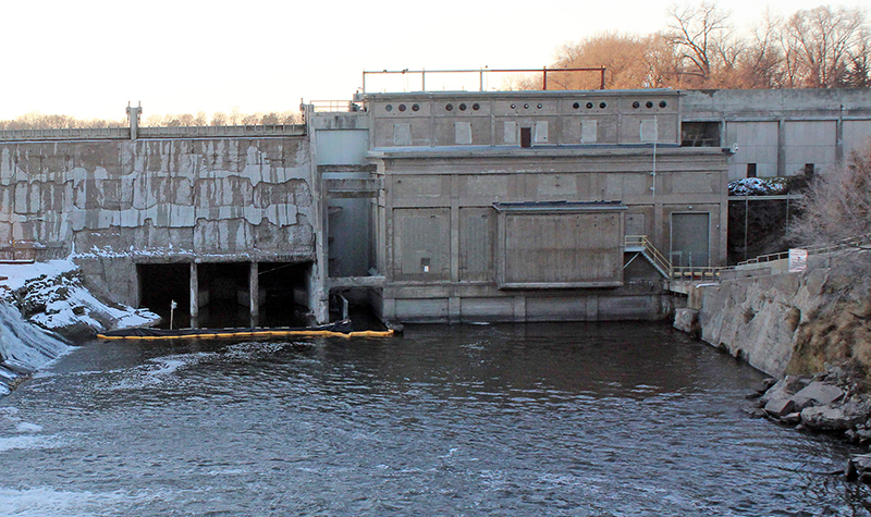
A great BIM case study involves our work to evaluate and update turbine operations at Byllesby Dam in southeast Minnesota. Dam owner Dakota County contracted with the team of Ayres, Hatch, MEP Associates, and Spaulding Consultants to design major turbine and powerhouse upgrades. The 1910 dam was built by the Ambursen Hydraulic Construction Co., which built a historic engineering style of dams in the early 20th century. Because Ambursen minimized concrete and only used it where the design loads were highest, Ambursen dams have very complex geometry with wall thicknesses changing every 10 feet vertically and at several points horizontally.
The project took many twists and turns and required a great deal of collaboration among the four consultants, so design development benefited greatly from the availability of highly detailed documentation of the existing condition and the many design updates along the way.
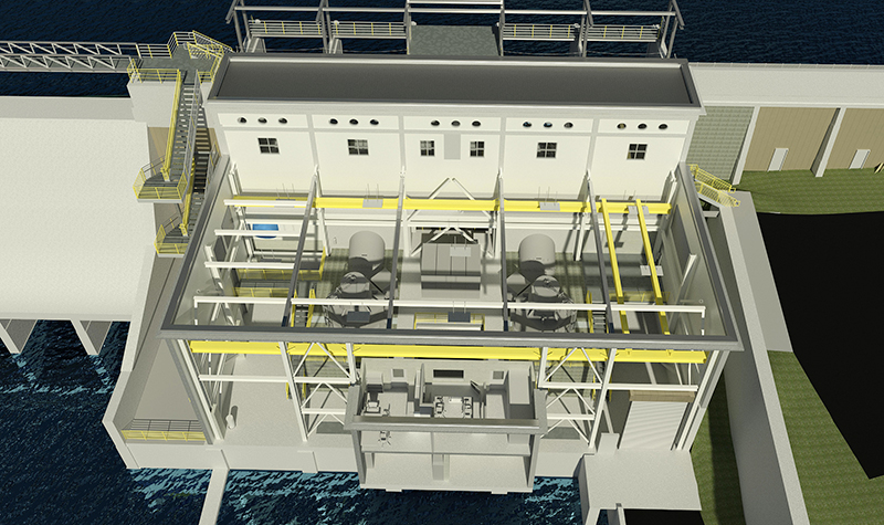
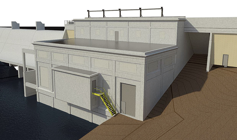
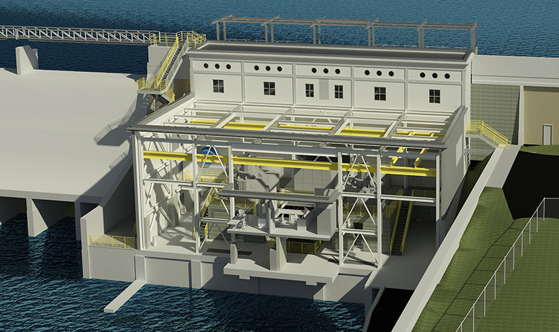
 Ayres provided 3D Revit models for a number of design alternatives. The architectural renderings show windows, lighting, concrete staining, and details necessary for the Minnesota State Historic Preservation Office (SHPO) to check visual conformity with early 1900s architecture. The Revit model included manufacturer models of purchased turbine and generator equipment, which allowed Ayres to check access and clearance and options for the arrangement of controls, plumbing, and wiring. Design work included concrete repairs, roof design, raceways, control room, repairs and enhancements for two buttresses, and structural supports and modifications to accommodate staged turbine installation.
In an earlier power production study, Ayres and Hatch had identified significant potential for long-term power production increases and gross revenue increases by replacing or modifying the 1911/1915 powerhouse equipment. The existing equipment was at the end of service life, so additional savings were expected by reduced maintenance and increased unit availability.
The team designed improvements to accommodate two SAXO turbines within the century-old powerhouse building shell. Design began with the assumption that the SHPO would not allow for changes in the dimensions or appearance of the existing powerhouse building. Another challenge recognized at the beginning was how to precisely fit new turbines into an existing building when bays that were thought to be of identical dimensions turned out to differ by several inches in width. The generators have to be lowered through roof hatches and have about 6 inches of spare room on either side for the installation. BIM helped the team confirm they had the necessary clearances.
 Byllesby Dam has an incomplete set of historical drawings, and those drawings don’t reflect as-built geometry. Ayres used an HD scanning laser to document the existing structure in the form of a dense point cloud representing the roof truss members, pier shapes, column thicknesses, and other measurements. Revit was used to translate that point data into a viewable format, allowing the team to check and recheck the many changes in the design that reacted to updates in SHPO guidance and accommodated the County’s preferences regarding roof insulation, wind load, and parapet wall height.
How Does BIM Help Handle Design Changes?
The design became a shared decision. The County stated the maximum extents of where turbines could go, dam safety engineers gave constraints on how deep into bedrock the contractor could excavate, and turbine vendors provided a guarantee of power generation. The accepted design yielded a good return on investment and an optimized bid, but as with many projects, the Byllesby Dam powerhouse replacement had to navigate many turns along the road to the ultimate destination. Revit and BIM smoothed the way:
- After the team completed the 30% stage of design and tried to match the aesthetic of the historic structure, SHPO asked the design team to differentiate the new powerhouse (no mimicry), so Ayres switched the design to colored precast panels with different window sizes and a steel interior frame. BIM allows the designer to click on an object and change, for example, “existing concrete” to “new precast” and then add further detail showing what the precast section looks like.
- At first Ayres thought four small generation units would be the cheapest to install, but after analyzing the generation efficiency and reduced maintenance costs of two larger units, the Revit model confirmed two large units would fit; the County picked the two-unit design.
- While a computational fluid dynamics model was completed by the manufacturer, the two-unit configuration presented several worries about combining flow. Four water intake bays feeding two units required bending flow and combining flow with a wye, possibly causing hydraulic vortices and flow field imbalances that could lead to generator vibrations and future bearing wear. To reduce risk of future problems, the design team pivoted from four penstocks with a wye to two penstocks with no wye. Sizing the penstocks required precise measurements on how much of a rectangular opening would fit between intake piers without damaging the Ambursen structure. The Revit model allowed exploration of options like replacing the building walls and roof, replacing the intake bays, and different dewatering options.
- The turbine manufacturer used the BIM to place all their equipment in areas that did not conflict with our new structural columns and concrete floors. Then the design team took the equipment layout and confirmed the piping and electrical cable runs did not conflict with stairs, walkways, cranes, and structural columns. Revit allows designers to run an automated interference check to detect spatial conflicts. The manufacturer and engineering iterations were many, including moving the generators upstream a few inches and rotating the main generator so that its main anchor bolts no longer protruded through a doorway lintel.
This project required shoehorning $4 million worth of generators from India, turbines from Austria, and switchgear from Mexico and Canada into a very tight space. Without BIM we might have had multiple “fit up” issues where the contractor would not have the right room to install equipment. Among the many issues BIM helped head off was the greater height of the generators, which meant the generators’ top caps (oil heads) would have been in the way of the overhead crane. We detected the situation during design, chose a thinner crane beam, and raised the roof a few inches. Thanks, BIM!
Contact Ayres’ water resources engineers for help with your dam project.


Post a comment: